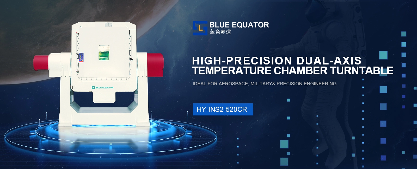
• Thermal rate positioning system for research and inertial sensor calibration on lab bench
  • Motion calibration stand with 520mm table and -55 to 150 degree thermal chamber for IMU test
  • Close up of high resolution encoder for 0.36 arcsec resolution and ±1 arcsec repeatability
  • Positioning system performing low drift rate test for FOG gyroscope characterization
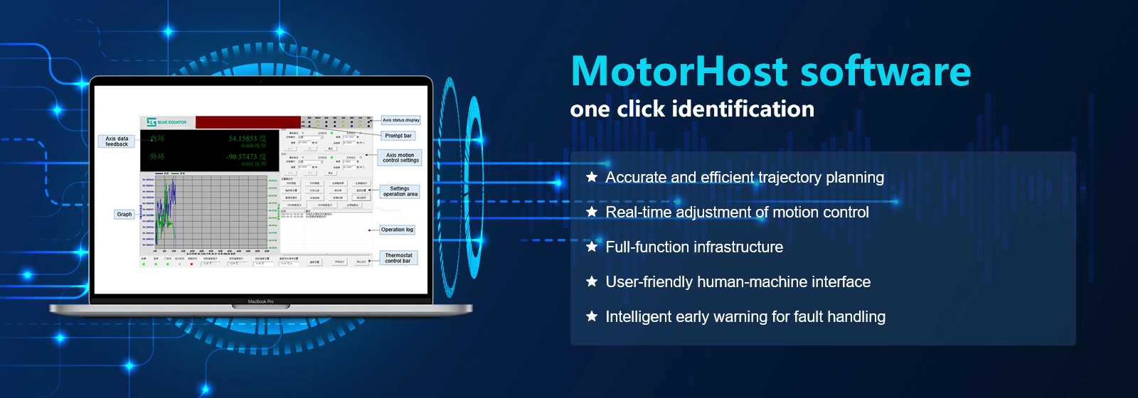
  • Automated control interface executing sensor calibration and research experiment sequence
  • Thermal rate positioning system for research and inertial sensor calibration on lab bench
  • Motion calibration stand with 520mm table and -55 to 150 degree thermal chamber for IMU test
  • Close up of high resolution encoder for 0.36 arcsec resolution and ±1 arcsec repeatability
  • Positioning system performing low drift rate test for FOG gyroscope characterization
  • Automated control interface executing sensor calibration and research experiment sequence

Thermal Rate Positioning System for Research and Inertial Sensor Calibration

No.HY-INS2-520CR
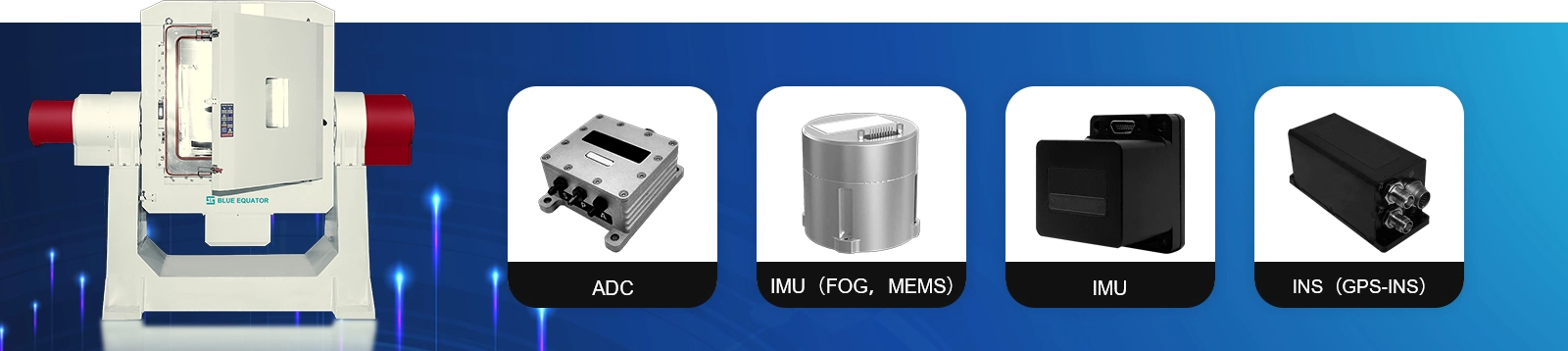
This high precision thermal rate positioning system functions as motion simulator and calibration stand for research and inertial sensor development. 40kg load capacity with Φ520mm table supports IMUs, FOGs, gyroscopes, and accelerometers. -55℃ to +150℃ thermal chamber with ±0.5℃ stability enables precise temperature characterization of inertial sensors. Perfect for inertial navigation technology R&D, MEMS sensor characterization, and academic research experiments.
Specifications
Load weight:
40KG
Load table size:
≥Φ520mm
Position accuracy:
≤±3 arc sec
Temperature range:
-55℃~+150℃
Download
View all downloads
  • Thermal rate positioning system for research and inertial sensor calibration on lab bench
  • Motion calibration stand with 520mm table and -55 to 150 degree thermal chamber for IMU test
  • Close up of high resolution encoder for 0.36 arcsec resolution and ±1 arcsec repeatability
  • Positioning system performing low drift rate test for FOG gyroscope characterization
  • Automated control interface executing sensor calibration and research experiment sequence

Description

Unit Under Test (UUT)
Load weight 40KG
Load height less than 350mm
Load table size ≥Φ520mm
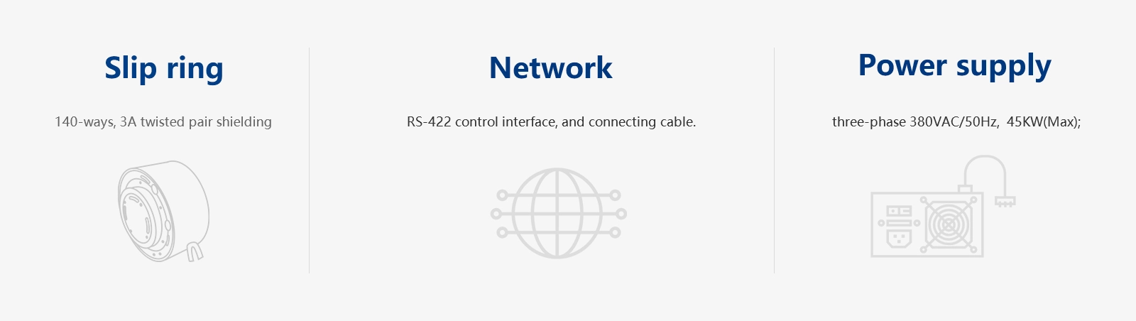
Slip rings to UUT Signal 140 ways, 3A @ 380VAC/50Hz,  45KW(Max)
Specifications
Inner Axis Outer Axis
Angular freedom continuous continuous
Position
Accuracy ≤±3 arc sec ≤±3 arc sec
Resolution 0.36 arc sec 0.36 arc sec
Repeatability ≤±1 arc sec ≤±1 arc sec
Rate
Range ±0.001 deg/sec ~ ±1000 deg/sec ±0.001 deg/sec ~ ±600 deg/sec
Accuracy and stability When θ1 deg/sec ≤1×10⁻³ (1 deg average)
When 1 deg/secθ10 deg/sec ≤1×10⁻⁴ (10 deg average);
When θ≥10 deg/sec ≤1×10⁻⁵ (360 deg average)
Dynamic
Acceleration(with load) 400 deg/sec2 100 deg/sec2
Mechanical
Wobble ≤±2 arc sec ≤±2 arc sec
Orthogonality ≤±2 arc sec ≤±2 arc sec
Temperature Chamber (TC)
Working volume 600*600*500mm
Temperature range -55℃~+150℃
Temperature stability ≤±0.5
Temperature change rate not less than 5/min, linear temperature change rate not less than 1/min;
Temperature deviation: ≤±2
Temperature gradient: ≤2
Dimensions
Machine platform dimensions 2500*1005*2100mm
Total weight 2300kg